 Hobart
WP6
Waste Equipment SystemHobart WP6 Waterpress
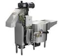
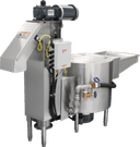
The Hobart WP6 waterpress separates slurry, returns process water to the pulper and discharges semi-dry pulp. Its stainless steel screw and screen assembly is removable without disconnecting the slurry or return-water piping.
Hobart WP6
17 compatible parts available
Genuine OEM Parts
Sourced from the manufacturer
Canadian Owned
Based in British Columbia
Canada-Wide Shipping
Every province and territory
24hr Quote Response
Answered by a real technician
Manuals & Documents
About the Hobart WP6
Overview
The Hobart WP6 is a commercial waterpress for use with a Hobart waste pulping system. It receives slurry from the pulper, squeezes out process water, returns that water to the pulper for reuse and discharges semi-dry pulp. Hobart states that the system can reduce waste volume by up to 88%. The WP6 is the waterpress component, not a complete pulper system by itself.
The unit is intended for foodservice waste applications that include schools, hospitals, clubs, fast food service, commercial restaurants, commissaries and airline in-flight kitchens. Hobart also lists confidential document destruction as an application. System layout and piping requirements affect the selected waterpress model; the manual identifies WP6 and WP9 as waterpress options for the broader WPR1200 system.
Key Features
- Six-inch-diameter gear-driven helical screw with an attached nylon brush, mounted inside a perforated cylindrical screen.
- Stainless steel screw, screen, housing, shell, wiper plates and removable access covers.
- Stainless steel wiper plates control pulp moisture content.
- The helical screw and screen assembly can be removed without disconnecting slurry or return-water piping.
- A standard chemical pump is included in the WP-6 Waterpress specification.
- The return pump set includes a motor, stainless steel impeller and mechanical seal to protect the stainless steel drive shaft.
- UL508-listed, prewired NEMA 4 stainless steel electrical control panel, field mounted.
- Programmable logic controls, a control-panel door-handle interlock and an electrical interlock on the hinged waterpress cover.
- Motorized and manual 1 1/2-inch NPT ball valves for system pump-down.
Specifications
- Model: WP-6 Waterpress, commonly identified as WP6.
- Waterpress function: Squeezes slurry, pumps return water to the pulper for reuse and discharges semi-dry pulp.
- Waste-volume reduction: Up to 88%.
- Waterpress motor: 3 H.P.; foot-mounted, totally enclosed and fan-cooled.
- Return-pump motor: Standard 5 H.P.; heavy-duty, foot-mounted, totally enclosed and fan-cooled. The specification notes that other horsepower is available and that motor sizing may vary with equipment location and system requirements.
- Standard return-pump capability: Pumps return water 300 feet horizontally and 15 feet vertically.
- Waterpress assembly: Stainless steel shell; 6-inch-diameter gear-driven helical screw with attached nylon brush; perforated cylindrical screen; stainless steel wiper plates; slurry inlet, return-water outlet and overflow connections; stainless steel access cover and removable access door.
- Discharge housing: Stainless steel, with gear reducer and stainless steel discharge chute.
- Base: Tubular steel structural members with stainless steel flanged feet; supports the waterpress assembly, discharge housing and return-pump set.
- Valves: Motorized and manual 1 1/2-inch NPT ball valves for system pump-down; field mounted.
- Controls: UL508-listed industrial control panel, prewired NEMA 4 stainless steel enclosure and programmable logic controls. The specification describes a main circuit breaker interlocked with the panel-door handle, nominal 115-volt magnetic controls, circuit breakers, magnetic starters and individual three-leg thermal overload protection for each motor.
- Electrical options listed: 200/60/3, 230/60/3 or 460/60/3. Confirm the installed unit's electrical service against its data plate.
- Safety interlock: The hinged waterpress cover interlock prevents operation, or turns the equipment off, if the cover on the discharge chute is raised.
- Optional configurations listed by Hobart: Chute extension for through-the-wall discharge, auxiliary base for elevating the waterpress, heated chute, flush-mounted control panel, bus communication and pulp-level detector.
Installation & Requirements
Plumbing and drains
The WPR1200 manual covers the waste system using a WP6 or WP9 waterpress. It states that the customer supplies the interconnecting slurry and return piping between the waterpress and pulper, as well as the waterpress overflow and drain lines to a floor sink or floor drain. Plumbing connections must comply with applicable sanitary, safety and plumbing codes. Use pressure-rated drainage fittings, and do not place external strain on Hobart equipment or piping. Protect the equipment and piping from freezing and condensation.
For a WP6, the waterpress fresh-water connection is a 1/2-inch NPT valve. Connect the hot-water supply to the manual shutoff valve on the piping assembly at the side of the waterpress. Incoming water pressure must be between 25 and 45 psig while flowing. Install 1 1/2-inch pipe from the waterpress auto-rinse drain on the return-piping assembly to a suitable floor drain. Use an open connection; do not connect directly to the drain or reduce the pipe size. The manual specifies a floor drain or floor sink at least 6 inches in size, subject to local code requirements, kept clear of but accessible to the unit.
Use the pipe sizes specified in the installation drawings. The manual calls for standard Type M copper piping for slurry and return lines, correct flow direction, and long-radius T-Y cleanouts or lateral fittings with 45-degree elbows. Install accessible cleanouts at turns and every 50 feet of straight pipe. Do not use 90-degree elbows or right-angle turns; the manual warns that these can cause jams. Avoid drastic elevation changes that could cause airlocks. Terminate slurry and return lines with union or flanged fittings, install a manual shutoff valve on incoming fresh-water lines, and pressure-test the piping for leaks at 150 psig.
Install hot- and cold-water hose bibs, with a heavy-duty hose and squeeze valve, where they are accessible for daily cleaning. The manual says these are installed by others. It also calls for a suitable open floor-drain connection for the pulper drain; do not make a direct plumbing connection or reduce the specified 2-inch pulper drain pipe.
Electrical and controls
Before installation, test the electrical service against the specifications on the machine data plate. The WP-6 specification lists 200/60/3, 230/60/3 and 460/60/3 electrical options. Hobart supplies prewired control panels, operator devices and electric valves. For the WPR1200 system installation, the manual specifies 1 1/4-inch watertight conduit between the wall-mounted control box and the prewired machine control box for motor and control wires; a 3/8-inch air line also runs in this conduit. Ground all electrical equipment. The manual identifies a nominal 115 VAC control circuit and says remote push-button stations and their mounting brackets are supplied and installed by others.
Operation
The manual's operating instructions apply to the WPR1200 waste system with its selected waterpress. Before starting, close the pulper drain valve, put the wall-mounted main power switch in the ON position and unlock the STOP button. Confirm that the pulper cover or undercounter cover plate is closed, the waterpress door is in place and the discharge-chute cover is lowered. Turn the Empty/Run selector to RUN. The system fills with water; when it reaches the proper level, the green Ready light on the Start button comes on. Press START and wait for a continuous return-water flow before feeding waste.
Feed waste continuously and uniformly. The manual says the feed rate should not exceed 60 pounds in a three-minute period; overfeeding reduces rated operating capacity. Open large plastic bags before feeding them, and feed one at a time because unopened bags can fill with air and float. Monitor return-water flow: a sharp reduction indicates the pulper is overloaded. Stop feeding for a few minutes until the flow resumes normally. Avoid feeding a large amount of greasy swill at once or overloading the pulper with bread or pastry; mix these with bulky waste such as paper or corrugated boxes. Foaming can result from water contaminants or waste materials such as glue in corrugated cardboard; a chemical defoaming agent may help, and the manual advises consulting the chemical supplier.
To shut down, leave the pulper running and turn the Empty/Run selector to EMPTY. The pulper stops automatically when the shutdown timer has timed out. Do not add waste during the Empty cycle. If feeding needs to resume after the cycle starts, the manual says to return the selector to RUN. Then press STOP and engage its locking attachment, turn the main switch on the remote control box to OFF, and open the drain valve.
Cleaning & Maintenance
The manual calls for regular daily cleaning and warns that missed cleaning can lead to an unsightly machine and odours. Shut down using the stated procedure. Before cleaning, disconnect electrical power at the main control box, tag the disconnect to indicate work is being done on the circuit, and wait for the pulper disk to stop completely. Keep hands out of the equipment while it is operating.
- Remove non-pulpable material from the pulper tank, taking care because glass or other sharp items may be present.
- Wash the tank interior with a hose, suitable brush, detergent and deodorant or another cleaning solution. Clean the underside of the upper-shell flange.
- Using water pressure of 25 to 45 psig, wash down the waterpress screen and interior walls of the waterpress and pulper tank. A long-handled nylon-bristle brush is recommended. Avoid spraying the chemical pump.
- Wipe down the equipment exterior. The manual says it is not necessary to dig out the plug of pulp remaining at the top of the waterpress screw.
- After cleaning, wash down the floor, close the drain valve and replace all removed parts before restarting.
The manual recommends draining dirty water after each meal cycle and keeping the pulp-receiving receptacle no taller than the bottom of the discharge chute. Empty the receptacle as necessary. It also states that the machine performs better with clean water.
Troubleshooting
The manual lists the following checks for the WPR1200 system. Disconnect power and follow lockout/tagout procedures before cleaning or servicing.
- System will not start: Reset a tripped supply circuit breaker; turn the main-control-box power handle ON; position the pulper cover and waterpress discharge-chute lid correctly; check that there is enough water; or reset a tripped overload.
- No water or insufficient water make-up: Turn on the water supply. Check that the drain valve is closed and repair it if it is leaking.
- Pulper jammed: Turn the machine off at the main control panel and clean it out if it has been overloaded. If scrap metal or heavy material is jamming the pulping disc, turn the machine off and remove the material. If it cannot be removed, call service.
- Waterpress jammed: Turn the machine off and remove residual pulp if the discharge-chute outlet is obstructed. Remove hardened waste material from the waterpress. If a full trash container is causing pulp to back up in the discharge chute, empty it and remove loose pulp from the chute.
- Machine will not drain or drains very slowly: Run the pulper until the unpulped material has been processed. If it will not process the material, turn the machine off and clean out the tank. Use water pressure to clear a clogged drain.
- Excessive foaming: The manual lists certain materials, including glossy paper, cardboard and potatoes, as possible causes and recommends adding a defoaming agent.
Applications
Hobart lists the WP-6 Waterpress for foodservice waste from schools, hospitals, clubs, fast food service, commercial restaurants, commissaries and airline in-flight kitchens, as well as confidential document destruction. The operating manual describes its role within a waste pulping system: the pulper processes waste into slurry, the WP6 squeezes and separates the slurry, return water is pumped back to the pulper, and semi-dry pulp leaves through the discharge chute.
Hobart WP6 Specifications
- Base
- Tubular steel members with stainless steel flanged feet
- Brush
- Attached nylon brush
- Model
- WP-6 Waterpress
- Shell
- Stainless steel
- Screen
- Perforated cylindrical screen
- Valves
- Motorized and manual 1 1/2 inch NPT ball valves for system pump-down; field-mounted
- Controls
- UL508-listed, prewired NEMA 4 electrical control panel; field-mounted
- Function
- Squeezes waste slurry, returns water to pulper for reuse, and discharges semi-dry pulp
- Screw type
- Gear-driven helical screw
- Manufacturer
- Hobart
- Wiper plates
- Stainless steel
- Access covers
- Stainless steel and removable
- Chemical pump
- Standard
- Control logic
- Programmable logic controls
- Screw diameter
- 6 inches
- Discharge chute
- Stainless steel
- Return pump set
- Includes motor, stainless steel impeller, and mechanical seal to protect stainless steel drive shaft
- Waterpress motor
- 3 H.P., foot-mounted, totally enclosed, fan-cooled
- Discharge housing
- Stainless steel
- Return pump motor
- 5 H.P., heavy-duty, foot-mounted, totally enclosed, fan-cooled; other H.P. available
- Electrical interlock
- Prevents operation or turns off equipment if hinged discharge-chute cover is raised
- Optional heated chute
- Available
- Waste volume reduction
- Up to 88%
- Incoming water pressure
- 25 psig to 45 psig flowing
- Optional auxiliary base
- For elevating waterpress
- Control panel components
- Main circuit breaker interlocked with panel door handle, nominal 115 volt magnetic controls, circuit breakers, magnetic starters, and individual three-leg thermal overload protection for each motor
- Optional chute extension
- For through-the-wall discharge
- Electrical specifications
- 200/60/3; 230/60/3; 460/60/3
- Screw and screen assembly
- Removable without disconnecting slurry or return water piping
- Optional bus communication
- Available
- Auto-rinse drain connection
- 1 1/2 inch pipe
- Optional pulp level detector
- Available
- Standard return pump capacity
- Pumps return water 300 feet horizontally and 15 feet vertically
- Waterpress fresh-water connection
- 1/2 inch NPT for WP6
- Optional flush-mounted control panel
- Available
Frequently Asked Questions
What does the Hobart WP6 do?+
Is the WP6 a complete waste pulping system?+
How much can the WP6 reduce waste volume?+
What motors are specified for the WP6?+
What electrical service does the WP6 require?+
What water connection does the WP6 need?+
How should operators feed waste into the system?+
How often should the system be cleaned?+
What should I check if the waterpress jams?+
What options are listed for the WP-6?+
Need Parts for This Model?
Get a free quote for parts, service, or maintenance for the Hobart WP6. We respond within 24 hours.
 Hobart
View all Hobart equipment →
Parts for the Hobart WP6
Browse genuine OEM components, gaskets, heating elements, thermostats, and replacement hardware guaranteed to fit this equipment.
 Available to Order
Hobart 00-316148 TRANSFORMER,300VA,208-230-460
Available to OrderHobart 00-936897 OVERLOAD,6-25 AMP
Available to OrderHobart 00-936865 CONTACTOR, AUX 4-POLE
Available to OrderHobart 00-316198 SWITCH,PRESSURE J400-449
Available to OrderHobart 00-316082 CIRCUIT BREAKER
 In Stock 360°
Hobart 00-913102-00428 KIT SEAL ASSY/GASKET/O-RING
Available to OrderHobart 00-316130 CONNECTOR - FLEX 3
Available to OrderHobart 00-316165 STRIP,TERMINAL,BLACK BLOCK
Available to OrderHobart 00-936885 SCREEN,TANK DRAIN
Available to OrderHobart 00-936896 FITTING,1/2MPTX3/4BARB FLEX
Available to OrderHobart 00-936907 KIT,DRAIN LINKAGE
Available to OrderHobart 00-936899 FUSE, 1 AMP
Available to OrderHobart 00-316387 CAP/COVER
 In Stock 360°
Hobart 00-936875 Switch, Timed Shutdown, Black Push Button
 Available to Order
Hobart 00-936868 PUMP, 3HP PUMP PAS MP
Available to OrderHobart 00-936881 VALVE,3/4 SOLENOID
 Available to Order