 Image not available
 Hobart
WS1000
Waste Equipment SystemHobart WS1000 Pulper and Water Press System
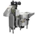
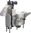
The Hobart WS1000 combines a pulper and water press to grind suitable food-service waste into slurry, then remove moisture and compact the pulp. Its process water is recycled to the pulper.
Hobart WS1000
113 compatible parts available
Genuine OEM Parts
Sourced from the manufacturer
Canadian Owned
Based in British Columbia
Canada-Wide Shipping
Every province and territory
24hr Quote Response
Answered by a real technician
Manuals & Documents
About the Hobart WS1000
Overview
The Hobart WS1000 is part of the WS Series Waste Equipment Systems. The system consists of a pulper, piping and a water press. In the pulper, a 5 horsepower motor drives carbide cutting edges that shred and grind suitable waste into a pumpable slurry. The slurry travels through piping to the water press, where a stainless steel screw squeezes out moisture, compacts the waste and lifts the semi-dry pulp to the discharge chute. Process water is recycled to the pulper.
The WS1000 is self-contained: the pulper and water press are connected and sit adjacent to one another. The manual lists left-to-right and right-to-left operation. It also describes an optional undercounter pulper installation with a water-tight trough connection; a silver-saver sink with a lift-out basket may be installed with the trough, and is supplied by others.
Key Features
- A 5 horsepower pulper motor and carbide cutting edges process grindable waste into slurry.
- The water press uses a stainless steel screw to separate moisture, compact waste and move semi-dry pulp to the discharge chute.
- Process water returns to the pulper for reuse.
- The pulper and water press are connected and adjacent as a self-contained system.
- Left-to-right and right-to-left operating arrangements are listed for the WS1000.
- An undercounter installation with a water-tight trough connection is described as an option in the manual.
Specifications
- Product type: Waste Equipment System.
- System components: pulper, piping and water press.
- Pulper motor: 5 horsepower.
- Pulper cutting edges: carbide.
- Water press screw: stainless steel.
- System materials: stainless steel components are specified in the manual.
- Process: waste is ground to pumpable slurry, dewatered and compacted; process water is recycled to the pulper.
- Operating direction: left-to-right or right-to-left.
- Model/control identifiers shown in the manual: WS1000 left-to-right, ML-110370; WS1000 right-to-left, ML-110371.
- Water connection: 1/2-inch NPT internal-thread connector at the bottom rear of the water press.
- Incoming water pressure: 25 to 45 psig while flowing.
- Parts catalog motor configurations for the WS Series list 5 hp, 3-phase pulper-drive motors for 240/480 V, 60 Hz or 200/380/415 V, 50 Hz; 208/380 V, 60 Hz; and 575 V, 60 Hz. Verify the individual machine data plate for its electrical service requirements.
- Optional chemical-feeder connection, when specified: maximum available pump current is 2.4 A at 200–240 V or 1.6 A at 380–575 V.
Installation & Requirements
Location and plumbing
The manual calls for the water press to be located near a floor drain. The floor should slope at least 1/4 inch per foot toward the drain. Provide space for machine operation, cleaning and service; the supplied manual excerpt does not give a numerical clearance requirement. Before installation, check that the electrical service agrees with the machine data plate on the front of the water press.
Connect the water supply to the 1/2-inch NPT internal-thread connector at the bottom rear of the water press, with a manual shut-off valve. Incoming pressure must be between 25 and 45 psig while flowing. Connect the water-press drain to a suitable drain in accordance with local code. The manual warns that plumbing connections must comply with applicable sanitary, safety and plumbing codes.
Electrical and optional chemical-feeder connections
The control box is remote from the pulper and water press. Terminal blocks are provided in the remote control box, identified as NEMA 12, and in the enclosure at the rear of the water press. Conduit and wiring are by others and must follow the electrical diagram inside the control box. The manual requires electrical and grounding connections to comply with applicable portions of the National Electrical Code and/or local electrical codes. Disconnect power at the supply and tag the disconnect before working on the circuit.
If the optional chemical feeder is installed by others, connect its pump outlet to the tube at the rear of the water press when that tube is specified. Connection points are available in the remote control box and on terminal blocks at the rear of the water press. Match line voltage to machine voltage, and use suitable wiring—not bell wire or lamp cord. The maximum available current for the chemical-feeder pump connection is 2.4 A at 200–240 V or 1.6 A at 380–575 V.
Operation
Feed suitable waste into the pulper so it can be ground into slurry and carried to the water press. A reduction in return-water flow indicates that the pulper is overloaded; stop feeding for a few minutes and wait for normal flow to resume. Avoid feeding a large amount of greasy swill at once, and do not overload the pulper with bread or pastry. Mix those materials with bulky waste such as corrugated boxes. The manual says the system performs better with clean, cold water and recommends draining dirty water after each meal cycle.
Keep the discharge receptacle at or below the bottom of the discharge chute and empty it as needed. Add corrugated boxes at regular intervals while processing. Feed heavy printed matter, computer cards, bulletins, computer printouts and catalogs gradually to avoid overloading. If waste arrives in large plastic bags, open the bags and feed them one at a time; unopened bags can trap air, float and interfere with operation.
Do not feed glass or metal containers. Sort them out of plastic bags because they are highly abrasive and accelerate machine wear; the manual recommends a can or bottle crusher for reducing their volume. Do not feed rags, mop heads, wooden crates, oyster or clam shells, or heavy uncooked bones, as the system cannot efficiently reduce their volume. Glossy-finished paper and high-glue-content waste can cause foam in the pulper. If foaming becomes excessive, the manual says anti-foaming chemicals and metering pumps are available from chemical supply companies.
Cleaning & Maintenance
Daily cleaning
The manual says cleaning takes only a few minutes daily but must be done regularly; missed cleaning can leave the machine unsightly and cause odours. A hose with a good-quality lever-operated nozzle should be available, preferably with hot water, for cleaning the equipment and surrounding area. At the end of the operating period, save paper trash or corrugated cardboard boxes and process them through the pulper. If the Clean Cycle option is fitted, press its button; the system processes the final load for 15 minutes and then shuts down automatically. Without that option, allow at least 10 minutes for the final paper or cardboard load to process. Press Stop and wait for the pulper disk to stop.
Before cleaning, disconnect electrical power at the main control box, tag the disconnect and wait for the pulper disk to come to a complete stop. Open the feed hood or pulper cover plate and remove floating material with a strainer or skim tool. Open the discharge chute and put remaining pulp in the waste dumpster. If the feed hood/tray option is fitted, remove its curtains from the clips. Open the drain valve and drain the machine, then scoop loose trash from the pulper into a trash container. Hose down the inside of the pulper tank and, where fitted, the feed hood and curtains.
Open and remove the trash box, empty it and clean it, then replace it. Remove the three water-press access doors and hose down the inside of the housing and screen; flush lightly with the hose. The manual says it is not necessary to dig out the pulp plug remaining at the top of the water-press screw. After cleaning, wash down the floor, close the drain valve, dispose of material removed from the trash box and replace all removed parts.
Maintenance
Keep motors free of dirt and do not restrict their ventilation openings. The water-press drive uses a close-coupled motor and speed reducer. The motor requires no lubrication maintenance. The speed-reducer gears run in an oil reservoir; the manual says a Hobart service technician should check oil level and quality every six months. For repairs or adjustments, the manual directs operators to contact a local Hobart-authorized service office.
Troubleshooting
Before clearing a jam or performing maintenance, turn the machine off at the main control panel; follow the manual’s power-disconnection and tagging warnings before working on the equipment.
- Machine will not start: Check for a tripped circuit breaker and replace the fuse or reset the breaker as appropriate. Make sure the main control-box power handle is on. Put the pulper cover, discharge-chute lid and discharge chute in their proper positions. If there is no water or not enough water, see the water-supply checks below.
- No water or no water make-up: Turn on the water supply. Close the drain valve, and repair it if it is leaking.
- Pulper jammed: An overloaded pulper or a pulping disk jammed by scrap metal or heavy material may be responsible. Turn the machine off at the main control panel and clean out the pulper. If material cannot be removed, call for service.
- Water press jammed: Check for an obstructed discharge-chute outlet, hardened waste in the water press, or a full trash container causing pulp to back up. Turn the machine off, remove residual pulp or hardened waste, empty the container and clear loose pulp from the discharge chute.
- Will not drain or drains very slowly: Possible causes include a full trash box, unpulped material in the pulper or a clogged drain hose. Turn the machine off. The manual says not to remove the trash box for this procedure; wear a protective glove and clean from inside the pulper tank. Run the pulper until material has been processed. If it will not process the material, turn the machine off and clean the tank. A plumber-installed clean-out plug can be removed so water pressure can be used to clear a drain-hose clog.
- Excessive foaming in the water press: Glossy paper, cardboard and potatoes can produce large amounts of foam. Add a defoaming agent, drain and refill the machine with fresh water, or turn the pulper off when not feeding it.
Applications
The WS1000 is intended for commercial food-service waste handling where grindable material can be fed gradually, processed as slurry and compacted into semi-dry pulp. The manual specifically discusses paper waste, corrugated cardboard and food-service waste, while identifying glass, metal containers, rags, mop heads, wooden crates, oyster or clam shells and heavy uncooked bones as unsuitable feed materials.
Hobart WS1000 Specifications
- Model
- WS1000
- Product Type
- Waste equipment system
- Cutting Edges
- Carbide
- Floor Drain Slope
- Minimum 1/4" per foot
- Operation Options
- Left-to-right or right-to-left
- Pulper Components
- Stainless steel
- Water Press Screw
- Stainless steel
- Pulper Motor Power
- 5 horsepower
- Installation Option
- Pulper can be installed undercounter with a water-tight trough connection
- Incoming Water Pressure
- 25–45 psig flowing
- Water Supply Connection
- 1/2" NPT internal-thread connector
- Chemical Feeder Connection Maximum Amps
- 2.4 Amp (200–240 Volts); 1.6 Amp (380–575 Volts)
Frequently Asked Questions
What does the Hobart WS1000 do?+
What are the main components of the WS1000?+
What water connection and pressure does the WS1000 require?+
Can the WS1000 be installed for either operating direction?+
What materials should not be put into the WS1000?+
What should I do if return-water flow drops during operation?+
Why might the WS1000 produce excessive foam?+
How often should the water-press speed reducer oil be checked?+
How do I clean the WS1000 at the end of a work period?+
Need Parts for This Model?
Get a free quote for parts, service, or maintenance for the Hobart WS1000. We respond within 24 hours.
 Hobart
View all Hobart equipment →
Parts for the Hobart WS1000
Browse genuine OEM components, gaskets, heating elements, thermostats, and replacement hardware guaranteed to fit this equipment.
 Available to Order
Hobart 00-329336-00002 PAD,RUBBER WAFFLE W/O HOLES
 Available to Order
Hobart 00-122837 RELAY GUARDIAN
 Available to Order
Hobart 00-748275 RETARDER,WELDMENT
Available to OrderHobart 01-234301-39800 ND,TOS-20 QUAD
 Available to Order
Hobart 00-087711-166-1 PLATE,START,BLACK
 Available to Order
Hobart 00-474581-00002 CASTING,CONE,FULL,MACH
 Available to Order
Hobart 00-475430 WELDMENT,SLURRY,6
Available to OrderHobart FP-088-24 FITTING,TUBE 1/2
 In Stock 360°
Hobart FE-022-28 Fuse, 250V, 0.5A
Available to OrderHobart SD-019-26 SCREW
 In Stock 360°
Hobart SC-067-23 Screw, Hex Head, 5/16-18 x 3/8"
 In Stock
Hobart 00-474405 PULL,DRAWER
 In Stock 360°
Hobart NS-013-25 Hex Nut, 3/8-16
 Available to Order
Hobart FE-025-23 FUSE,600V,10A
 Available to Order
Hobart 00-473831 RETARDER WELDMENT
 In Stock 360°
Hobart SC-022-43 Screw, Slotted, Flat Head, 5/16-18 x 1/2"
Available to OrderHobart 00-294500-00028 TRANSFORMER,50 VA
 Available to Order
Hobart 00-474124-00001 MOTOR,3/4 HP,208-230/460/60/3
Available to OrderHobart SC-123-59 SCREW,SET 3/8-24 X 3/8
 Available to Order
Hobart 00-473862 CAP
 In Stock 360°
Hobart SC-008-09 Screw, Slotted Round Head, 10-24 x 3/8"
 Available to Order
Hobart 00-473783 NOZZLE
 Available to Order
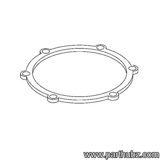
Hobart 00-223605-00001 HOUSING GASKET
 Available to Order